
Signalling
LOCAL POSITION INDICATION
The valve local position indication is a stainless steel plate, directly linked to the actuator housing in order to provide the valve position by the interpretation of the valve stem position arrow mark.
This option can also be substituted with a beacon that provides a single 360º visual position monitoring.
DIRECT INDICATION
Position Indicator Boxes
 The position indicator boxes are used for transmitting the remote reading of position of the valve. They are mounted in the upper part of the actuator.
The reading of the position can be digital, by means of contacts which indicates the extreme positions of the valve, or analogical, by means of a potentiometer which indicates the continuous reading of the valve´s position.
These elements of position signaling are located inside a watertight box with protection IP-67. As an option, IP-68 protection could be supplied.
In addition to the remote reading of position, the valve in all cases also provides a local visual reading.
INDIRECT INDICATION
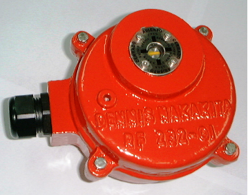
Flow Meters Indicator
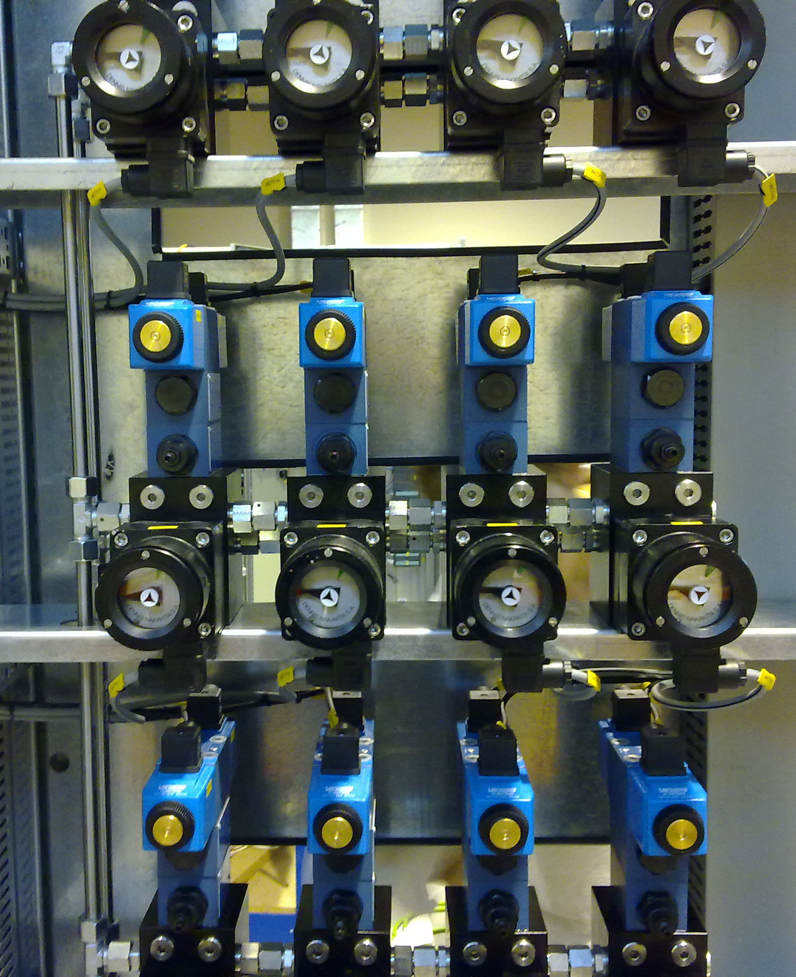 The valve position indicator FLOWMETER is a combined unit with mounting surface for directional control valves NG 06 according to ISO 4401. In detail the module consists of a hydraulic manifold, a gear type volume counter and an indicator.
The Flowmeter position indication devise is designed to locally visualize as well as remotely indicate the position of hydraulically operated butterfly valves. The Flow-meter is a combined unit that consists by a directional valve and it´s control modules, together with the hydraulic gear driven components (a hydraulic manifold, a gear type volume counter and an indicator).
This option is particularly convenient when the valve is located in a submerged/non accessible place, or in hazardous areas, avoiding the preparation for the special cabling and the costs involved. In such way, the valve position is obtained by measuring the actual quantity of oil flowing to or from the valve actuator.
The flow-meter is intended to match the specific actuator displacement, therefore the indication is proportional to the displaced oil and thus to the punctual valve position.
Pressure Switch
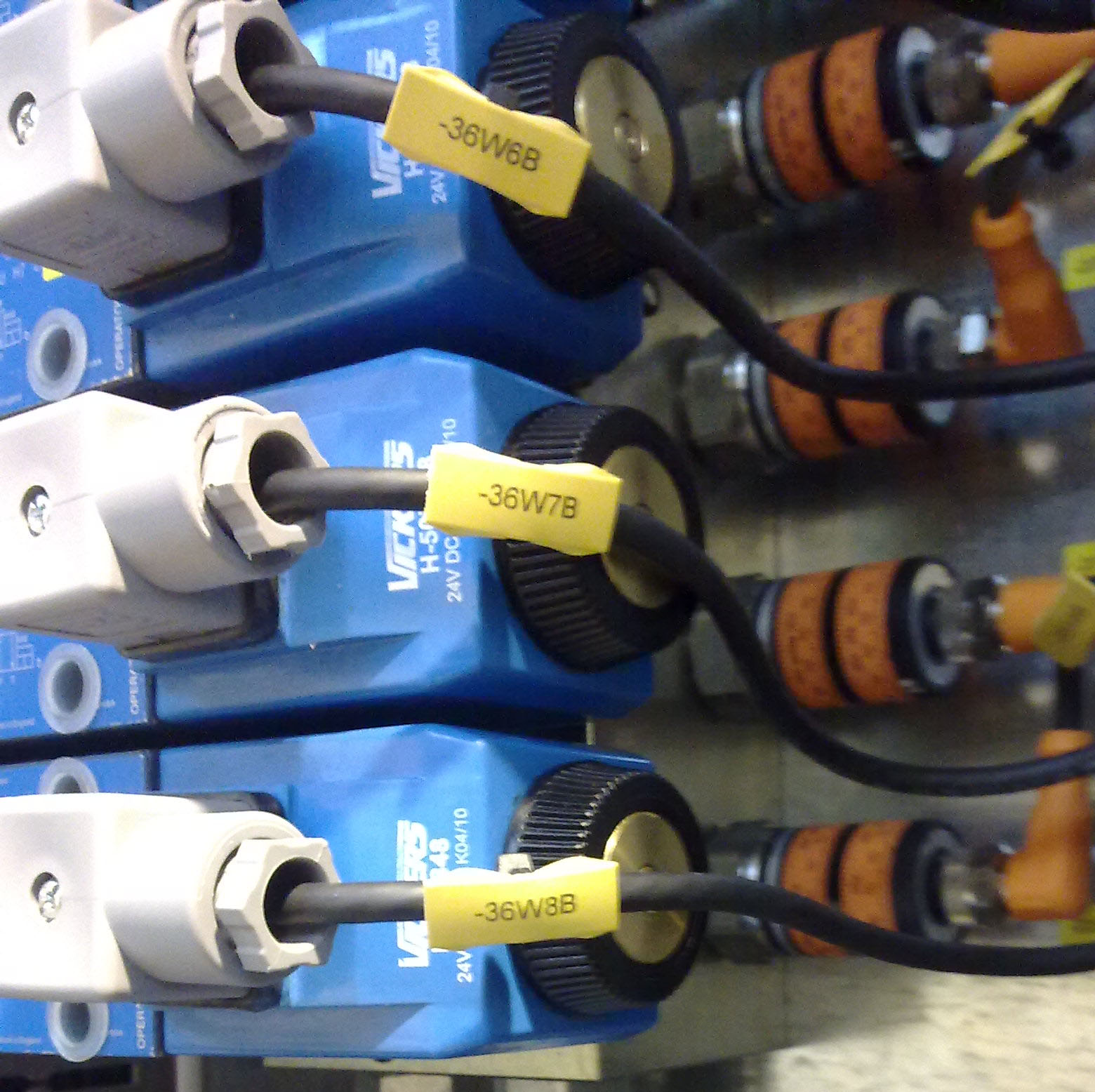 This remote indication is only intended for open/shut valve operation modality. This configuration can be used in both, double acting and single acting actuators by means of a 4/2 type solenoid control valve. For double acting actuators are also applicable 4/3 type solenoid control valve.
In this option, a pressure switch is installed in the pilot piping lines that connects the solenoid valve racks and the hydraulic actuators. Once the solenoid valves allows the oil to flow into the actuator chamber and it reaches its final position by filling the Open or Close hydraulic circuit, the pressure activates the electrical relay in the pressure switches, confirming in such a away, the valve commanded operation.
This configuration also allows having a valve locking alarm by matching the pressure switch activation with the solenoid valve last command in the HMI control panel. The event of a mismatch generally represents system oil leaking or an actuator malfunction.